
In this article, you will find 5 categories:
- Plugin requirements
- Install the REVIT plugin
- Insert point cloud in REVIT
- Point cloud management
- Insert the sources of a project in REVIT
- Management of bubbles (360 images) of a point cloud.
1. Plugin requirements
Minimum Configuration:
Processor: Dual-core 2 GHz or higher
RAM: Minimum 8 GB or more
Graphics Card: Nvidia Quadro or GeForce 1 GB + OpenGL 4.5 or higher versions (latest drivers must be installed)
Hard Drive: 1 GB or more of free storage space
Recommended Configuration:
Processor: Intel® i-Series, Xeon®, AMD® Ryzen, Ryzen Threadripper PRO. 2.5 GHz or higher
RAM: Minimum 16 GB or more
Graphics Card: Nvidia Quadro or GeForce 1 GB + OpenGL 4.5 or higher versions (latest drivers must be installed)
Hard Drive: 5 GB or more of free storage space
2. Install the REVIT plugin
Once you receive the installer, open it (double-click the file) to display the following interface:

In this window, select the version of Revit on which you want to install the plugin (2022 or 2023). Click on the desired version in the selection rectangle (red rectangle), of the photo below:

After choosing the version, click "Next" located at the bottom right of the interface. The interface will then change to display the following photo:

At any time, you can return to your previous selection by clicking on "Previous", or cancel the current download by clicking on "Cancel", to continue the installation, click on "Install".

For more information on canceling the download, see the "Cancel the download in progress" section. If a conflict occurs during installation, see "Running Revit Conflict".
The download will start automatically and you will arrive on this interface:

Congratulations ! You have finished installing the Revit plug-in. Click the "Finish" button (blue frame) at the bottom right of the interface to finalize the process.
Cancel the current download:
If you clicked on the “Cancel” button located at the bottom right of each installer interface, you will see the following interface:

You have two options: click "Yes" to cancel the installation of the Revit plugin, or click "No" to return to the previous interface.

Conflict, Revit is running:
If a conflict occurs during installation, you will see the following interface:

In this case, you can choose to continue the download by automatically closing the Revit application. Please note that any projects currently open in Revit will not be saved and will be lost. Make sure you have saved your work before continuing. You can also choose to continue the installation without closing the conflicting applications. However, this will cause the installation to fail with the following message:

Finally, you can click "Cancel" to cancel the installation. For more information on canceling, see the "Cancel the current download" section. You can also click "Next", which will by default perform the same action as continuing the installation by closing the Revit application.
3. Insert a point cloud in REVIT
If the Revit plugin is not installed on your computer, you can first go to the “Revit plugin installation” category and then return to this category after this operation.
Please note that with these plugins you can serve any point cloud on the platform. First, open a project from the main menu by clicking on the project image. If no project is available, go to the “ Create a project ” article.
After you have a project opened, open the export menu and select streaming.

We now have access to the broadcast window, select the point cloud you want to broadcast as well as Autodesk Revit software.
Click "Generate" to get the broadcast code.

To copy the code, click on the copy button.

Then open Autodesk REVIT with the previously added plugin. If it is not yet added, go to the “ Revit plugin installation” category.
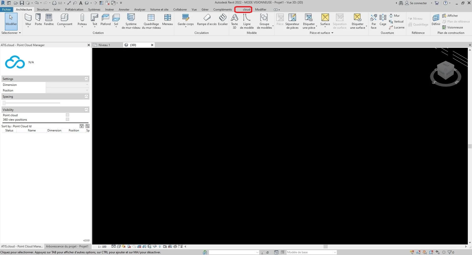
In your Revit project, click on “cloud” in the toolbar located at the top.
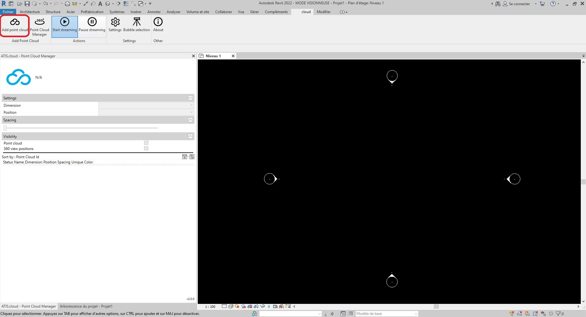
Click on “cloud streamer” located in the “Add Point Cloud” category in the toolbar at the top of the screen.
Following this action, a dialog box appeared on the screen, click on the notepad icon to the right of the trash can button.
For information, the code generated from the site named “streaming code” corresponds to the “Access code” field on Revit. In addition, you can delete this field at any time by clicking on the delete button symbolized by a trash can.

You can then configure the dimension of the point cloud. The dimension is the type of display it will have.
For information, all the point cloud settings can be modified even after the addition thanks to the “ Point Cloud Manager ”.
There are currently five compatible dimension types.
- Colors : It is used to represent the color of each point in the point cloud. The red, green, and blue channels are used to represent the color of the dot, while the alpha channel is used to represent the transparency or opacity of the dot. The use of color in LiDAR point clouds can be useful for visualization and interpretation purposes, as it can provide additional information about the properties of the objects and surfaces represented by the points. For example, in vegetation mapping, the color of the points can be used to distinguish between different types of vegetation or to identify areas with high or low vegetation density.
- Intensity : It represents the strength or amplitude of the signal that was received by a sensor or device when the point was captured. In some cases, the intensity is related to the reflectance of the object at that point. For example, in a LiDAR point cloud, the intensity value represents the amount of laser light that has been reflected back to the sensor by the object. In this case, a higher Intensity value would indicate a surface that reflects more light, such as a white wall, while a lower Intensity value would indicate a surface that reflects less light, such as a black car. In other cases, the intensity may represent a different physical quantity. For example, in a photographic point cloud, intensity can represent the brightness of a pixel in the original image that was used to generate the point cloud.
- Classification : Will only work with compatible point clouds . The purpose of classification is to group similar points into meaningful categories, such as soil, vegetation, buildings, and other objects.
- Height : It represents the height or vertical position of each point. Elevation data is important in many point cloud applications, such as topographic mapping, flood modeling, urban planning, and infrastructure design.
- Point Source ID : This identifies the specific laser sensor that generated the point. Each laser sensor in a LiDAR system has a unique identifier or number, and this information is recorded in the point cloud data to enable analysis and quality control. Point source identification is especially useful in situations where multiple LiDAR sensors are used to capture a single scene or area. By identifying which sensor generated each point, it is possible to perform quality checks on the data and ensure that the data is correctly aligned and registered between the different sensors. This is especially important in applications such as forestry, where multiple LiDAR sensors can be used to capture data from different angles and perspectives. On our platform, the point source id is used to store the source analysis id, allowing users to easily track which analysis each point in the point cloud originated from. For example, if multiple scans were performed on the same area using a 3D laser scanner, each scan could be assigned a unique scan ID and the point source ID attribute for each point in the cloud points could be set to the corresponding scan ID.
To select the desired dimension, click in the selection rectangle to the right of the text “Dimension”.

Click "Load Point Cloud" to initialize the point cloud data.

Change the insert settings in Revit to your preference. You can adjust the spacing between points with the "Spacing" slider and choose the position of the point cloud in the project by selecting one of three options: "Center to Center", "Internal Origin", or "At the Shared Site".
- Center to Center : This option places the point cloud using the center of the viewport as a reference point.
- Internal origin : This option positions the point cloud using the internal origin of the cloud as a reference point. The internal origin is usually defined by the coordinate system of the point cloud itself. Using this option, the point cloud will be positioned according to its internal origin rather than the origin of the Revit project. This can be useful when you need to align the point cloud to its own internal coordinate system.
- At the shared site : This option places the point cloud at the location of the shared site. Shared site refers to a common geographic location on which multiple projects can be based. Using this option, the point cloud will be positioned according to the coordinates of the shared site. This can be useful when working on projects based on a common site and want to align the point cloud to that shared location.
- Auto – Origin to Last Placed : Revit places the next imported point cloud consistently with the previously imported point cloud. This option becomes activated after inserting a first point cloud. You can move this first cloud, for example, in order to align it correctly with the elements of the model. If you have additional point clouds created on the same site and in the same coordinate system as the first one, it is recommended to use this option to insert the additional point clouds. The new point clouds will then be correctly positioned relative to the first.
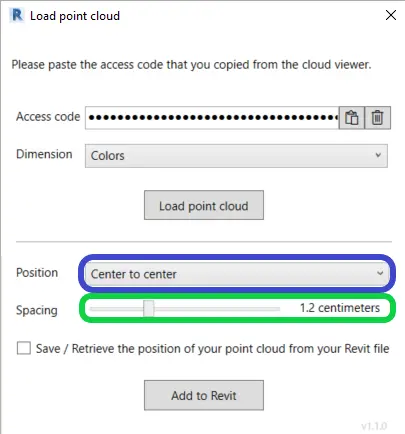
Once the configuration is complete, click "Add to Revit" to insert the point cloud into Revit.

Stop or Start point streaming:
In the toolbar, in the “Action” category, you have two buttons that allow you to either start point streaming or stop it.
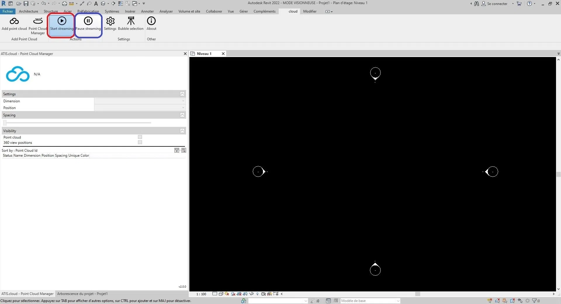
Point streaming is a feature that allows points to arrive from the cloud little by little according to a certain organization. However, this operation requires a permanent internet connection and requires certain resources from the host machine.
This is why you can stop by clicking on “Stop streaming” or restart by clicking on “Start streaming” the point streaming.
Clear storage space:
The plugin may experience operational issues if your computer's disk space becomes full. That's why, in the "Settings" button located in the "cloud" menu bar under the "Settings" category, you can clear the storage space reserved for the Revit plugin. First, click on "Settings"
For information, the clouds will visually disappear from Revit, this is normal when you start the point streaming, the point clouds will reappear (go to the Stop or Start the point streaming section to start the point streaming).
Congratulation ! You have now inserted a point cloud into Revit from the streamed data.
For more information on managing point cloud settings, see the "Point Cloud Manager" category.
From this window, you can also specify the maximum value of GPU memory to be used and the maximum value of disk space not to be exceeded by the plugin.
To learn more about adding web project sources in Revit, please see the "Add Sources" category.
4. Point cloud management
If the Revit plugin is not installed on your computer, you can first go to the “ Revit plugin installation ” category and then return to this category after this operation.
- Tip: To fully follow the instructions in this article, we recommend that you first add a point cloud. If this is not done, go to the category “ Insert a point cloud in Revit ”
The “Point Cloud Manager” is a graphical interface allowing to modify the parameters of each point cloud of the Revit project from the website. This window allows to move, to resize the interface as well as to anchor it to one side of the Revit screen.
To begin, click on a point cloud located in the “Point Cloud Manager” window. If the interface is not displayed, click on the “Point Cloud Manager” button located in the “Cloud” toolbar in the “Add Point Cloud” category.
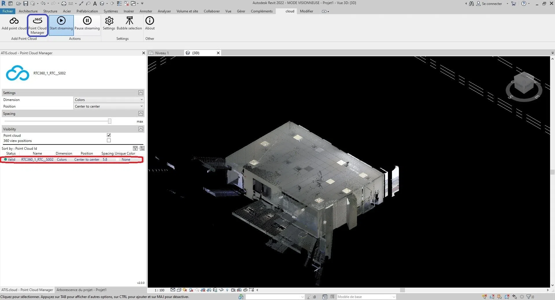
Part of the “Point Cloud Manager” interface appeared. The interface is split like this:
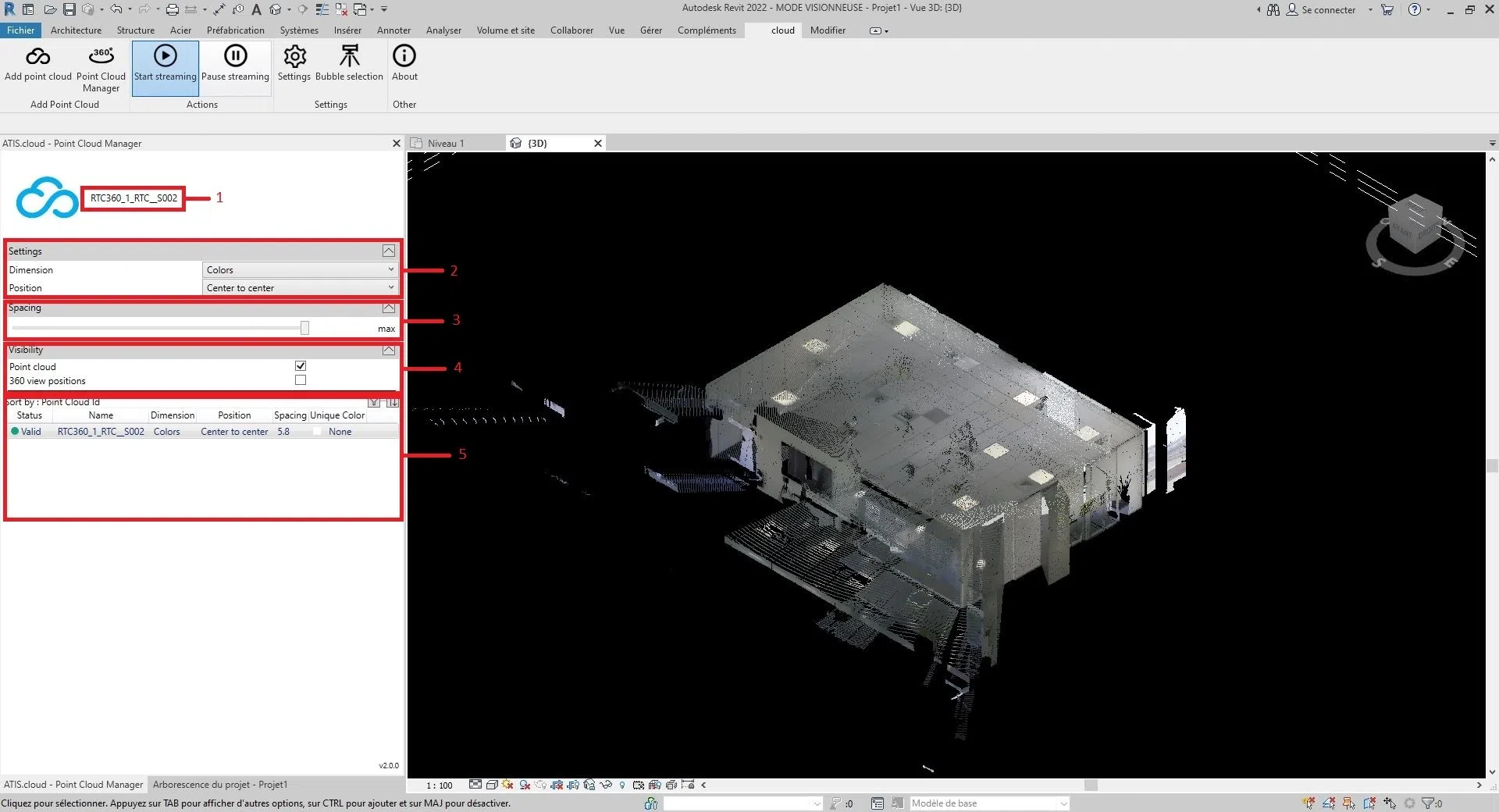
1: Name of the cloud selected, the name displayed is the same as that of the web project
2: Characteristics of the cloud such as the dimension and the position of the cloud
3: Spacing of each point of the cloud
4: Point cloud and scanners visibility parameter (for more information on scanners, go to the article “Scanner Revit”)
5: All the clouds inserted through the Revit plugin, it allows to see at a glance the main parameters of each cloud as well as to sort them.
- Trick :
- You can fold and unfold sections using the arrow button to the right of each section;
- You can resize the size between part 6 and the rest by holding down and then moving the mouse over the black bar located between the “Visibility” section and part 6.
You can now modify each parameter of each point cloud.
- The dimension of the cloud, go to the section “Change the dimension”;
- The position of the cloud, go to the section “Edit position”;
- The distance between the points of the cloud, go to the section “Modify the spacing”;
- The visibility of the cloud or scanners, go to the “Change visibility” section.
Change dimension:
To modify the selected dimension, click on the selection box to the right of “Dimension”.

There are six sizes to choose from:
Colors, Intensity, Classification, Height, Point Source ID and Unique Color.
- Colors : It is used to represent the color of each point in the point cloud. The red, green, and blue channels are used to represent the color of the dot, while the alpha channel is used to represent the transparency or opacity of the dot. The use of color in LiDAR point clouds can be useful for visualization and interpretation purposes, as it can provide additional information about the properties of the objects and surfaces represented by the points. For example, in vegetation mapping, the color of the points can be used to distinguish between different types of vegetation or to identify areas with high or low vegetation density.
- Intensity : It represents the strength or amplitude of the signal that was received by a sensor or device when the point was captured. In some cases, the intensity is related to the reflectance of the object at that point. For example, in a LiDAR point cloud, the intensity value represents the amount of laser light that has been reflected back to the sensor by the object. In this case, a higher Intensity value would indicate a surface that reflects more light, such as a white wall, while a lower Intensity value would indicate a surface that reflects less light, such as a black car. In other cases, the intensity may represent a different physical quantity. For example, in a photographic point cloud, intensity can represent the brightness of a pixel in the original image that was used to generate the point cloud.
- Classification : Will only work with compatible point clouds . The purpose of classification is to group similar points into meaningful categories, such as soil, vegetation, buildings, and other objects.
- Height : It represents the height or vertical position of each point. Elevation data is important in many point cloud applications, such as topographic mapping, flood modeling, urban planning, and infrastructure design. By analyzing elevation data, it is possible to create accurate and detailed digital elevation models (DEMs) that can be used for a wide range of geospatial analysis and visualization purposes.
- Point Source ID : This identifies the specific laser sensor that generated the point. Each laser sensor in a LiDAR system has a unique identifier or number, and this information is recorded in the point cloud data to enable analysis and quality control. Point source identification is especially useful in situations where multiple LiDAR sensors are used to capture a single scene or area. By identifying which sensor generated each point, it is possible to perform quality checks on the data and ensure that the data is correctly aligned and registered between the different sensors. This is especially important in applications such as forestry, where multiple LiDAR sensors can be used to capture data from different angles and perspectives. On our platform, the point source id is used to store the source analysis id, allowing users to easily track which analysis each point in the point cloud originated from. For example, if multiple scans were performed on the same area using a 3D laser scanner, each scan could be assigned a unique scan ID and the point source ID attribute for each point in the cloud points could be set to the corresponding scan ID.
- Unique Color: The objective of the “Unique Color” dimension is to be able to color the point cloud with a unique color defined by the user.
Change position:
To modify the selected position, click on the selection box to the right of “Position”.
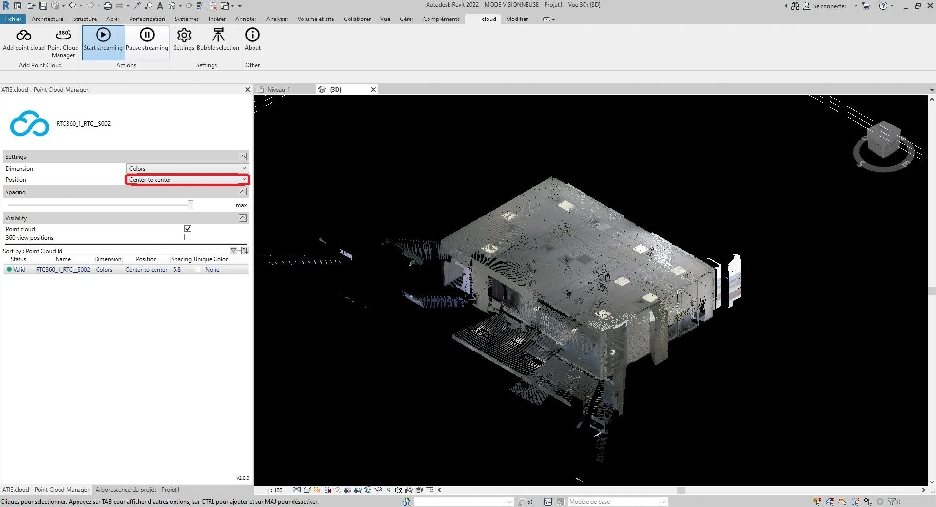
You will have the choice between these three options:
"Center to Center", "Internal Origin", or "At the Shared Site".
- Center to Center : This option places the point cloud using the center of the viewport as a reference point.
- Internal origin : This option positions the point cloud using the internal origin of the cloud as a reference point. The internal origin is usually defined by the coordinate system of the point cloud itself. Using this option, the point cloud will be positioned according to its internal origin rather than the origin of the Revit project. This can be useful when you need to align the point cloud to its own internal coordinate system.
- At the shared site : This option places the point cloud at the location of the shared site. Shared site refers to a common geographic location on which multiple projects can be based. Using this option, the point cloud will be positioned according to the coordinates of the shared site. This can be useful when working on projects based on a common site and want to align the point cloud to that shared location.
- Auto – Origin to Last Placed : Revit places the next imported point cloud consistently with the previously imported point cloud. This option becomes activated after inserting a first point cloud. You can move this first cloud, for example, in order to align it correctly with the elements of the model. If you have additional point clouds created on the same site and in the same coordinate system as the first one, it is recommended to use this option to insert the additional point clouds. The new point clouds will then be correctly positioned relative to the first.
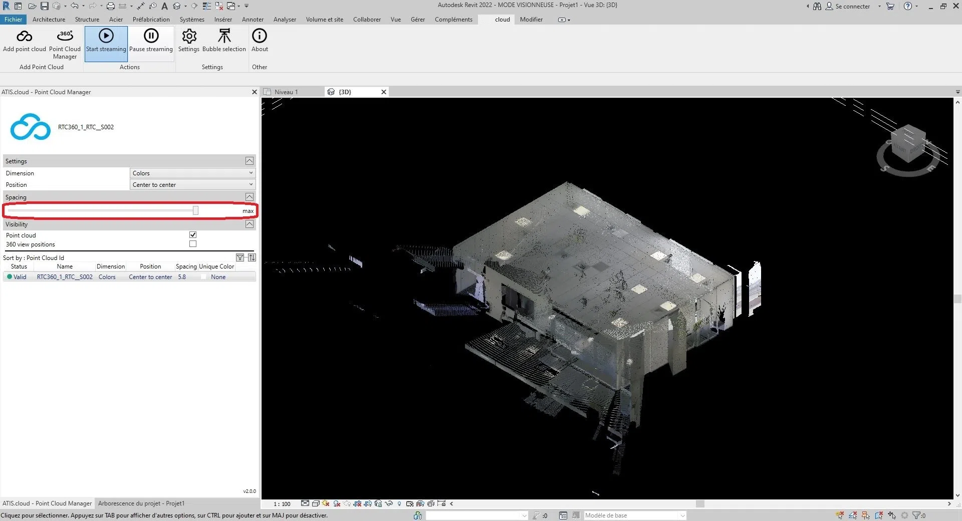
Change spacing:
To modify the spacing between the points of the cloud, move the bar of the “Spacing” section.
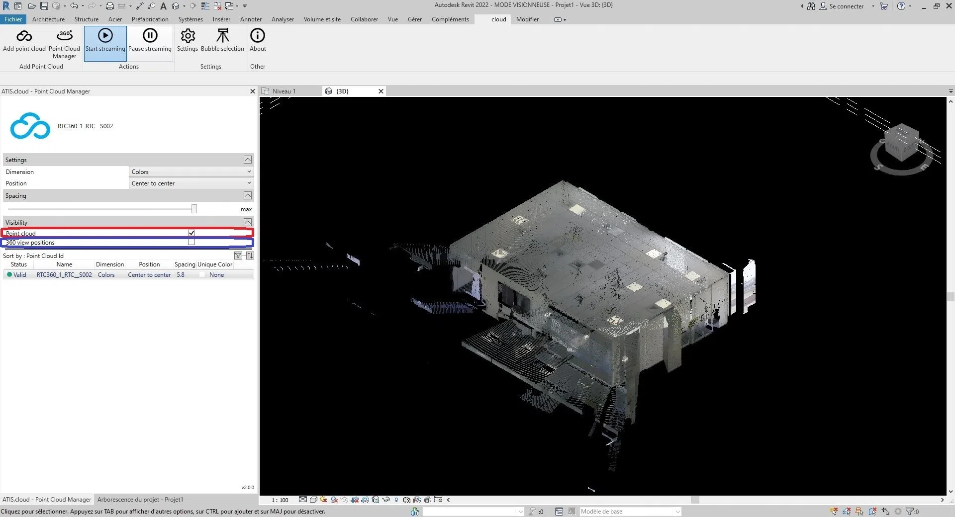
Change visibility:
To change the visibility, you have two options. Or, you can show/hide the point cloud by checking/unchecking the box to the right of “Point Cloud” in the “Visibility” section. Or, you can show/hide the point cloud scanners by checking/unchecking the box to the right of “360 View” in the “Visibility” section. (The visibility is the same between the different views of the project)
- Tips:
- Scanner information is in the “ Bubble management ” category.
- To zoom on a point cloud in the viewer, simply double-click on the corresponding cloud.
Congratulation ! You know everything about the “Point Cloud Manager” interface.
To learn more about the interaction between the website and Revit or more generally about the scanners, please consult the article " Bubble management ".
5. Insert project sources into REVIT
If the Revit plugin is not installed on your computer, you can first go to the “Revit plugin installation” category and then return to this category after this operation.
To add sources to a project, you must first add a point cloud. If it is not already done, go to the category “Insert a point cloud in Revit”.
After some time, following the addition of the point cloud, a message informing you of the detection of sources will appear. (time varies with the number of clouds on the project and their sizes)
Please note that this dialog box may be hidden behind an open tab on your computer.

You then have the possibility of adding all the sources of the project by clicking on “Yes” or of refusing the addition by clicking on “No”.
Attention, this action is irreversible, to be able to reinsert the sources, it is necessary to delete a cloud resulting from the project where the sources are located then to follow the instructions of this article.

Bravo, you have inserted the sources of a web project.
For more information on managing point cloud settings, see the "Point Cloud Manager" category.
6. Management of bubbles (360 images) of a point cloud
If the Revit plugin is not installed on your computer, you can first go to the “Revit plugin installation” category and then return to this category after this operation.
- Tip: To fully follow the instructions in this article, we recommend that you have previously followed the “Point Cloud Manager” category to display the scanners.
Scanners on Revit are 3D objects inserted at the same time as the point cloud, with the difference that they are invisible by default. It allows, thanks to a manipulation, to change the camera of the viewer of the website. They are represented by blue bubbles on the site and by a scanner in Revit.


You are informed when connecting or disconnecting between Revit and the website by a dialog box located at the bottom right of the web viewer.
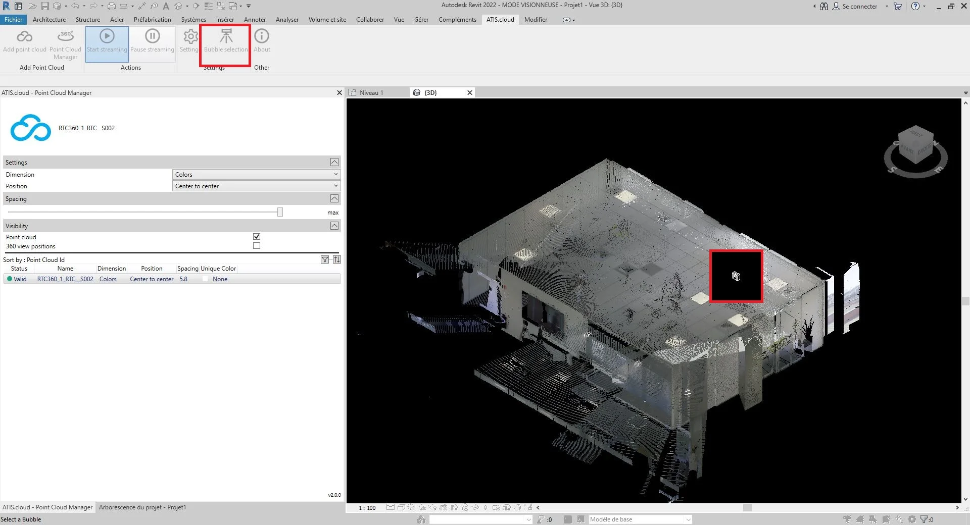
Once the connection is established, display the scanners of a point cloud, then press "Bubble Selection".
- Tip: To see the scanners directly without the point cloud obstructing vision, uncheck the visibility of the point cloud and make the scanners visible.
If the action was performed correctly, the mouse will go into selection mode.
You can exit this mode by pressing escape.
Select a scanner by clicking on it.
The view on the web viewer has been modified by the scanner, select in Revit.

- Information :
- If the web page was closed while using Revit, a web tab automatically opening the project will be created.
- It is recommended to close the viewer by clicking on the name located at the top left to return to the home page. If another method is used to exit the web page, the connection between Revit and the web application may not open for about ten minutes.
Congratulation ! You know how to change the point of view on the website through Revit.
7. Uninstall the REVIT plugin
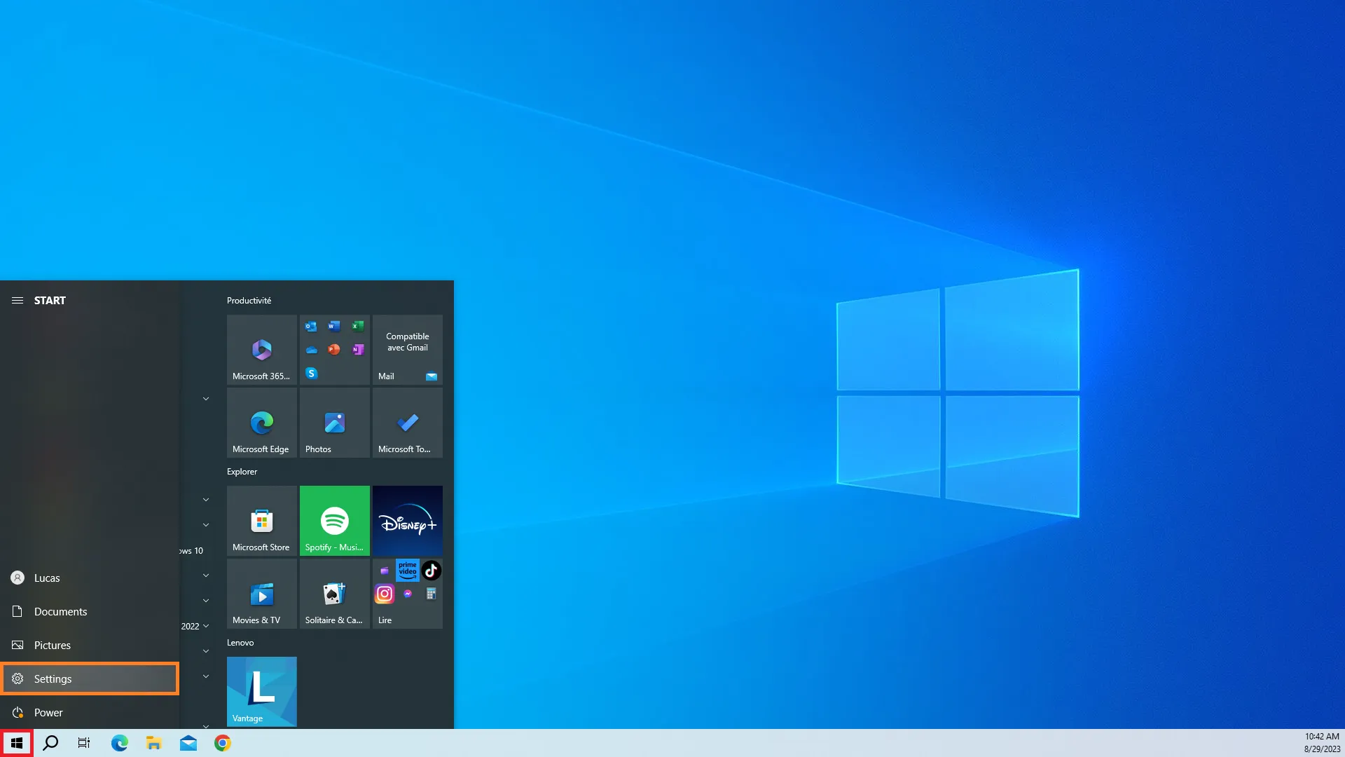
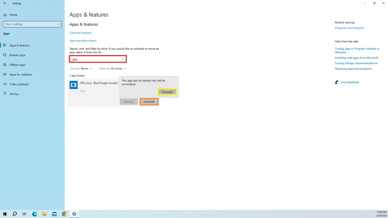
Start by opening your computer's settings, you can find those in the Windows Menu.
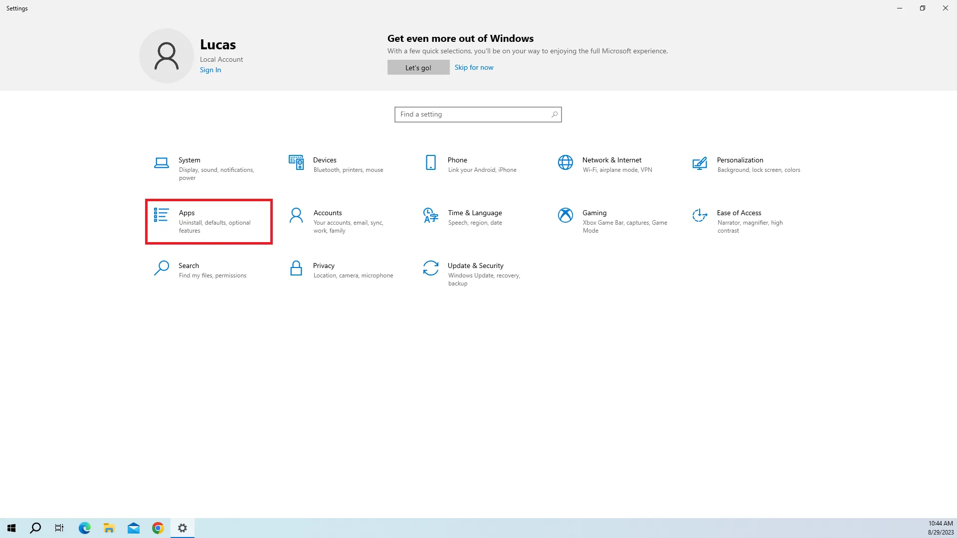
Open you Apps settings.
Search for “atis” and click Uninstall, a pop-up will appear, click Uninstall again to continue.
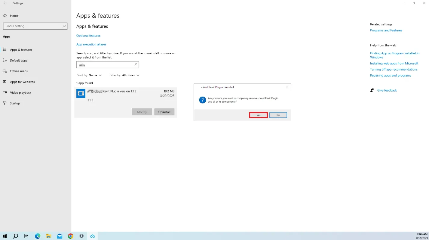
Click Yes to confirm the plugin suppression.
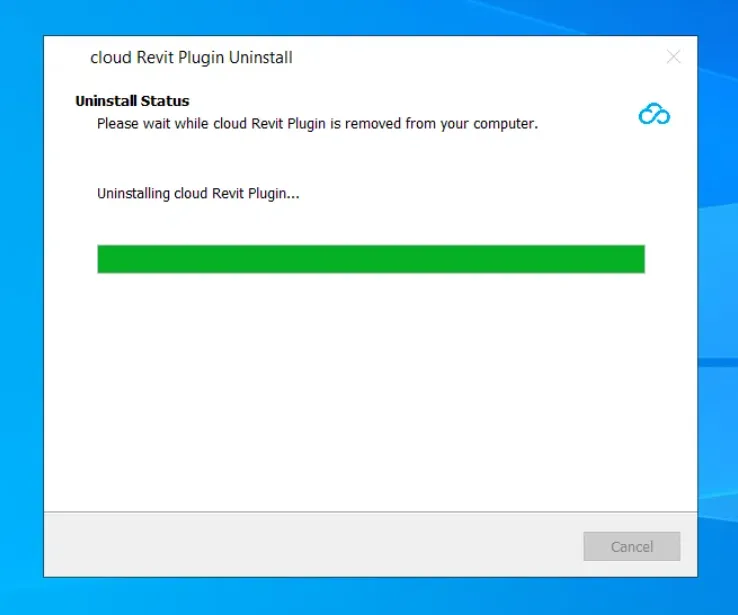
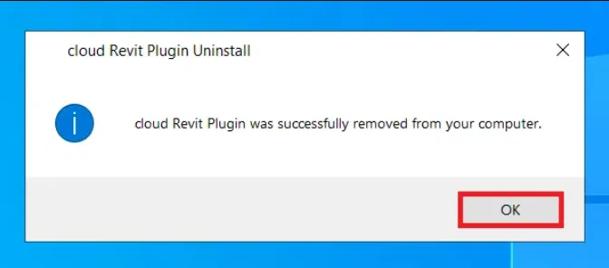
Wait for the process to finish and click Ok. The plugin has now been uninstalled. You can always install it again later by downloading it again.
In case of problem or difficulty, do not hesitate to contact the platform team.