The ATIS.cad interface
Overview
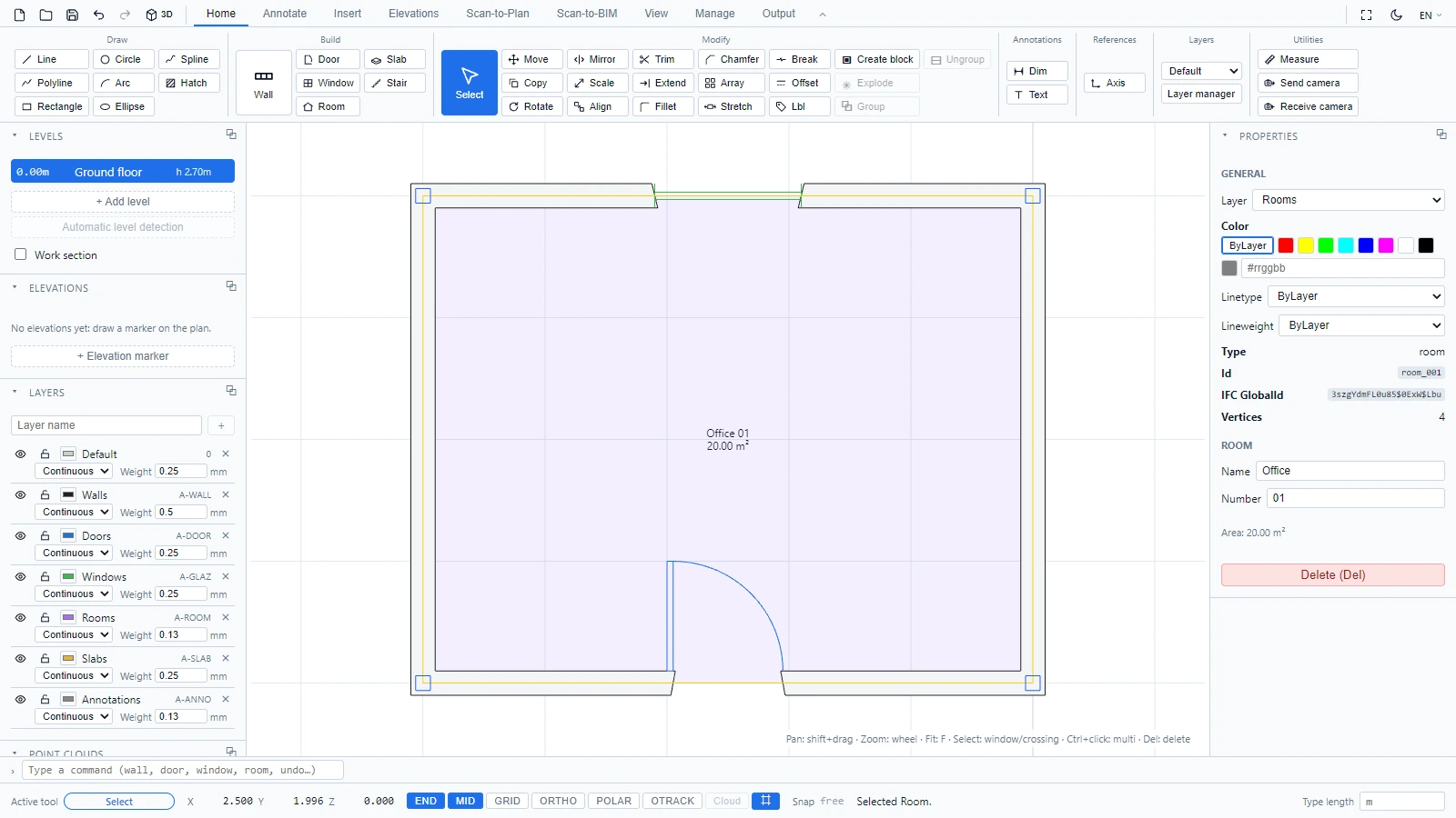
The workspace follows the layout of desktop CAD applications: a ribbon at the top, panels on the sides, the drawing area in the center and a command line at the bottom. If you have used AutoCAD or Revit, you will find the same vocabulary here (layers, dimensions, levels, families).
Quick access toolbar

The small toolbar at the very top left is always visible. From left to right:
- New: start an empty project.
- Open: load a project file (.cad.json).
- Save: download the current project as a .cad.json file.
- Undo / Redo: also available with Ctrl+Z and Ctrl+Y.
- 3D / 2D: switch between the plan view and the 3D view.
The ribbon

Tools are grouped into eight tabs:
| Tab | What you find there |
|---|---|
| Home | Drawing tools (Line, Polyline, Rectangle, Circle, Arc, Ellipse, Spline, Hatch), building objects (Wall, Door, Window, Slab, Stair, Room), modify tools (Move, Copy, Rotate, Mirror, Scale, Align, Trim, Extend, Offset, Fillet, Break), blocks and groups, quick access to dimensions and text, the axis tool, the layer selector and Measure |
| Annotate | All dimension types (Dim, Continue, Baseline, Radius, Diameter, Angular), Text and Leader |
| Insert | Import DWG / Import DXF with a unit override, image and PDF underlays, point clouds |
| Scan-to-Plan | Generate a 2D plan from a point cloud (depends on your subscription) |
| Scan-to-BIM | Generate a BIM model from a point cloud (depends on your subscription) |
| View | Zoom extents, 3D toggle, and the Palettes group to show or hide every panel |
| Manage | Project templates and document palettes such as Schedules |
| Output | PDF export, Export DXF, Export DWG, Export IFC |
The arrow button at the right end of the tab row minimizes the ribbon to its tabs. Click it again to restore the full ribbon.
Left panels: Levels, Layers, Point clouds
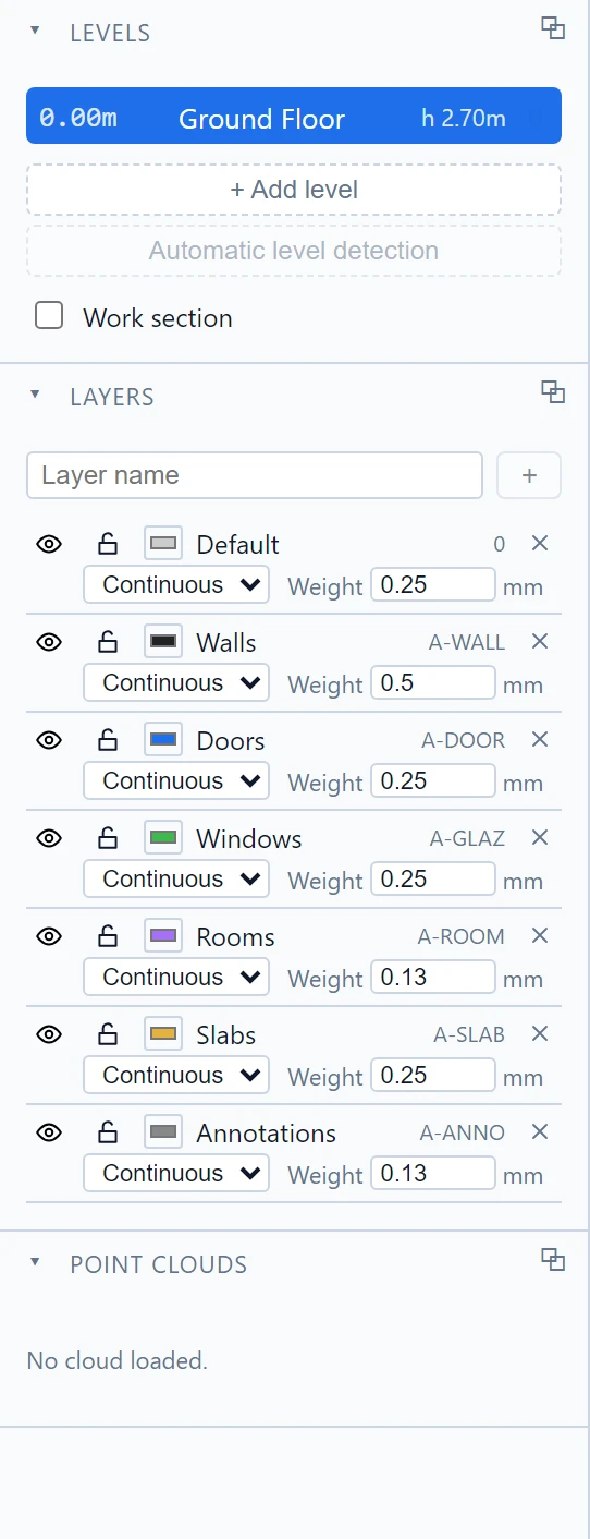
- Levels lists the storeys of your project. Each level shows its elevation and height. From here you add levels, run the automatic level detection on a point cloud, or enable a work section.
- Layers works like AutoCAD layers, with industry standard names (A-WALL, A-DOOR, A-GLAZ...). For each layer you control visibility (the eye), locking (the padlock), color, linetype and line weight. Objects you draw land on the layer that matches their type.
- Point clouds lists the loaded scans.
Properties panel
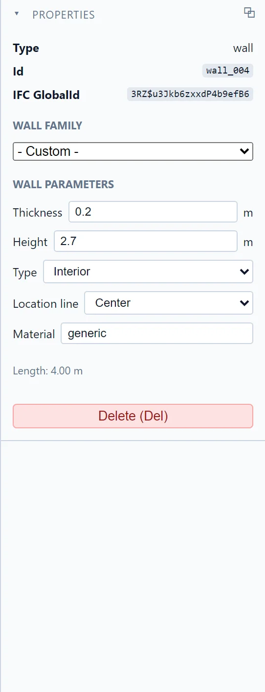
The Properties panel on the right reflects the current selection. For a wall you can change its family, thickness, height, interior or exterior type, location line and material. For a room, its name and number. With no selection, the panel simply invites you to pick an entity.
Command line and status bar

The command line accepts tool names, like in AutoCAD: type wall, circle or undo and press Enter. The up arrow recalls your previous commands, and the AutoCAD short codes work too (see Keyboard shortcuts and the command line).
The status bar below it shows, from left to right:
- The active tool.
- The cursor coordinates (X, Y, and Z in 3D).
- The snap toggles: END (endpoints), MID (midpoints), GRID, ORTHO and Cloud (point cloud snapping, enabled when a scan is loaded).
- The current snap state and tool messages, for example "Selected wall."
- The unit used when you type lengths.
Arrange the workspace
Every panel can be shown or hidden from View > Palettes. Reset layout puts everything back in its default place. The moon button at the top right switches the editor to dark mode, and the language selector next to it changes the interface language.
If you have any questions or need further information, please contact the technical team.